In this article (and video above), we break down the equilibrium of rigid bodies, zooming in on how to figure out support reactions at a roller. We take you through each step to make it easy to understand and apply in solving support forces in complicated structures.
Question:
Consider the loaded system shown below with supports at A, B, C and D. What is the reaction force at D due to the applied 6kN load?


Explanation:
Draw the free-body diagrams of the individual elements:
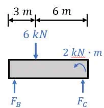
To start solving our problem, let’s draw free-body diagrams for the parts of the system. First, let’s isolate the small beam on the v-shaped structure. We’ll include the known forces: a 6kN force 3 meters from the left and a 2kNm moment at the far right end. We also need to consider the reaction forces (labeled FB and FC) from the supporting roller and pin. I’ve defined upward as positive for these forces to balance the downward 6kN force, but you could have chosen downward as positive too. Just be consistent with your force directions in both diagrams.
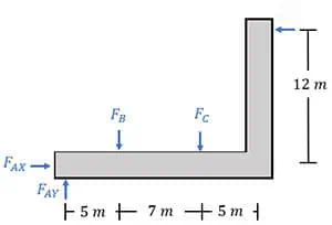
These forces compress the beam, affecting the second element similarly. In the diagrams, we’ll depict these forces as downward to show their compressive nature consistently across both. This way, we correctly connect the two diagrams.
Next, we’ll include the support reaction FAY. I’ve chosen FAY to act upward to balance forces FB and FC. It’s crucial to remember force FAX because there’s another force, FD, acting horizontally. Therefore, the pin support at A must counteract this force, unlike what we observed in our initial free-body diagram where no other horizontal forces required a reaction force at pin C.
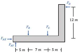
Lastly, we introduce the main force, FD. It’s crucial to remember that FD can only act to the left because of the roller support. Once we have these diagrams ready, we can begin solving for the unknown forces. Since the second diagram lacks any known forces, we’ll focus on the first diagram to start our analysis.
To determine the unknown force FB, we’ll balance moments around point C. Using anti-clockwise as the positive direction, we consider the 6kN force applied at 6 meters in the positive direction and the 2kNm moment about point C also in the positive direction. The unknown force FB, located 9 meters from point C, contributes a clockwise moment. Notably, force FC is excluded from this calculation as it acts directly at point C, resulting in a negligible moment due to its zero distance from the point. Therefore, by considering these factors, we can solve for FB effectively.
The sum of these moments all equal zero, allowing us to solve for FB, and we find that it is equal to 4.222 kN.
To find force FC, we use a vertical force balance. With upwards as positive, forces FB and FC are positive, and we subtract the 6kN downward force from our equation.
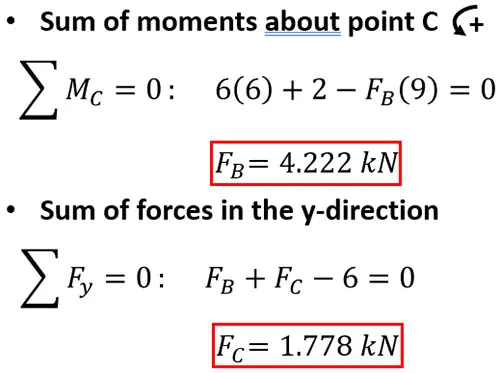
The total of these forces adds up to zero. When we replace force FB with 4.222 kN, we calculate force FC to be 1.778 kN. With all the unknown forces in our first free-body diagram figured out, we can proceed to the next part.
In the second free-body diagram, you might think to find force FAY first, as it’s the only unknown force in the y-direction. However, upon closer look, we can directly solve for force FD by balancing moments about point A. This way, we avoid calculating the reaction forces at A.
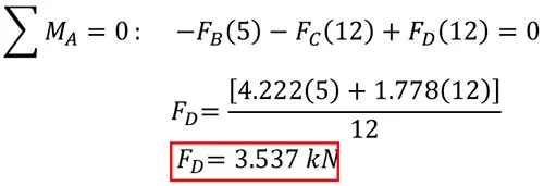
Using anti-clockwise as our positive direction, forces FB and FC create negative moments around point A at distances of 5 metres and 7 metres, respectively. The unknown force FD creates a positive (anti-clockwise) moment around point A at a distance of 12 metres. Therefore, our final equation is:

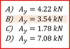
By substituting forces FB and FC, we find that the reaction force FD is 3.537 kN.
Answer:
The correct answer is B.
Final Remarks:
1.Draw clear and accurate free-body diagrams
2.Identify the type of supports (pin, roller, fixed).
3.Apply the equations of equilibrium (∑FX=0, ∑Fy=0, ∑M=0) carefully.
4.Consider different loading conditions and configurations for practice.
This Episode Is Brought to You by PPI
PPI has helped engineers achieve their licensing goals since 1975. Passing the FE and PE exams can open doors to career advancement and new opportunities. Check out PPI’s wide range of prep options, including Live Online courses, OnDemand courses, and digital study tools to help prepare you to pass your licensing exam here.
I hope you found this article helpful. In upcoming articles, I will solve some more PE exam practice problems and answer other questions from our subscribers. Pass the PE Exam videos will publish weekly, so be sure to click the subscribe button so you don’t miss something that could make a substantial difference in your exam result.
Lastly, I encourage you to ask questions in the comments of this video, or on this page and I’ll read and respond to them in future videos. So, if there’s a specific topic you want me to cover or answer, we have you covered.
I’ll see you next week… on Pass the FE Exam
Anthony Fasano, P.E.
Engineering Management Institute
Author of Engineer Your Own Success

Leave a Reply