In this article (and video above), we tackle a key structural engineering topic from the FE Exam: bending moment calculation for a loaded 20-foot beam. Using mathematical models and real-world examples, we walk through the bending moment calculations and discuss their significance in structural design. Whether you’re a student or a professional engineer, this article and video will help you strengthen your understanding of fundamental structural principles for the FE Exam.
Question:
A simply supported beam with a span of 20 feet is subjected to two loadings. A concentrated point load of 10 kips is applied 5 feet from the left support (point A), and a uniformly distributed load of 2 kips/ft acts continuously along the entire length of the beam. Determine the maximum bending moment in the beam using a bending moment calculation.
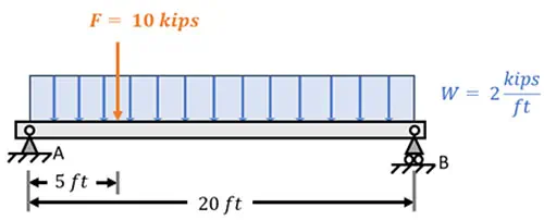
In today’s problem, we are tasked with analyzing a \(20\,\text{ft}\) long simply supported beam subjected to both a point load and a uniformly distributed load. The point load is applied at a distance of \(5\,\text{ft}\) from support \(A\), while the uniformly distributed load of \(2\,\text{kips/ft}\) is applied across the entire span of the beam. Our goal is to determine the maximum bending moment in the beam and its location.
Explanation:
In today’s problem, we are tasked with analysing a 20 ft long simply supported beam subjected to both a point load and a uniformly distributed load. The point load is applied at a distance of 5 ft from support A, while the uniformly distributed load of 2 kips/ft is applied across the entire span of the beam. Our goal is to perform a bending moment calculation to determine the maximum bending moment in the beam and its location.
To find the maximum moment in the beam due to the applied loads, we first need to determine the beam’s reactions at its supports. We label these loads R_A and R_B respectively. For convenience, we can also label our applied point load as F and the distributed loading as W.
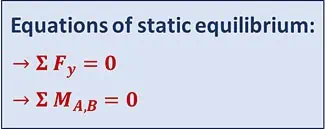
With all the forces accounted for, we can move on to applying the equations of static equilibrium. These equations are based on the fundamental principle that the sum of the vertical forces in a system must equal zero, and the sum of the moments about any point in the system must also equal zero.
\(\sum F_y = 0\)
\(\sum M_{A,B} = 0\)
Let’s find an equivalent load for the distributed force so we can apply this first equation. The total load intensity from the distributed load is calculated as the intensity of the load, \(2\,\text{kips/ft}\), multiplied by the beam’s length \(20\,\text{ft}\). This gives us an equivalent load of \(40\,\text{kips}\).
\(F_w = R_A \cdot L\)
\(F_w = 40\,\text{kips}\)
This represents the total load if the distributed loading were concentrated at the center of the beam as a single point load.
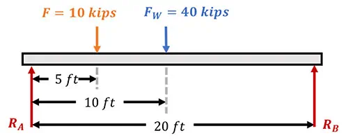
Next, with this equivalent load known, we calculate the reactions at the supports. To find the reaction at point \(B\), we take the moment about point \(A\) and set the sum of the moments equal to zero. Here, we take a moment in the clockwise direction to be positive’
\(\sum M_A = 0 \quad \circlearrowright^+\)
The moment at point A due to the point load, is \(10\,\text{kips}\), multiplied by the distance to this point, which is \(5\,\text{ft}\). Similarly, the moment due to the uniformly distributed load is equal to the equivalent load, \(40\,\text{kips}\), multiplied by the distance from point \(A\) to the beam’s center, at \(10\,\text{ft}\). Lastly, we account for our unknown load, \(R_B\), which is applied at a distance of \(20\,\text{ft}\) from point \(A\).
\(10(5) + 40(10) – R_B (20) = 0\)
We reorder this equation to solve for the reaction force, \(R_B\), and find that it has a value of \(22.5\,\text{kips}\).
\(R_B = 22.5\,\text{kips}\)
Now, we construct the equation for vertical force equilibrium, taking an upward force as positive.’
\(\sum F_y = 0 \quad \uparrow^+\)
Our equilibrium equation then becomes:
\(R_A – F – F_w + R_B = 0\)
Substituting the values of these variables and rearranging to solve for \(R_A\), we find that it has a value of \(27.5\,\text{kips}\).
\(R_A – 10 – 40 + 22.5 = 0\)
\(R_A = 27.5\,\text{kips}\)
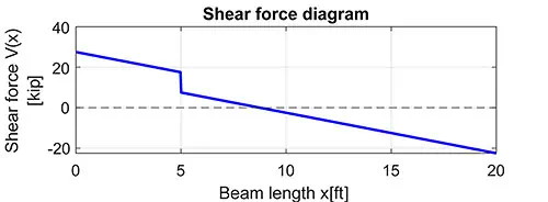
Now that we have calculated the reactions at the supports, we can proceed by analyzing the shear force along the length of the beam by moving from the left end, at support \(A\), to the right end, at support \(B\).
At point \(A\), the shear force starts with the reaction force from the support, which we’ve already found as \(27.5\,\text{kips}\).
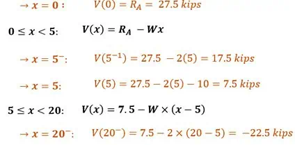
\(V(0) = R_A = 27.5\,\text{kips}\)
Then, as we move to the right from support \(A\), the uniformly distributed load steadily reduces the shear force. Since the load is \(2\,\text{kips/ft}\), the shear decreases at that constant rate. Mathematically, the shear force between \(x = 0\,\text{ft}\) and \(x = 5\,\text{ft}\) can be described as \(R_A – wx\).
\(V(x) = R_A – wx,\quad 0 \leq x < 5\)
‘Here, \(R_A = 27.5\,\text{kips}\) and \(w = 2\,\text{kips/ft}\). We can use this shear formula to calculate the shear force in the beam at the location \(x = 5\,\text{ft}\). And remember, when we substitute 5 ft here, the formula is giving us the shear force at the point just before this location, and not exactly at it.
\(V(5^-) = 27.5 – 2(5) = 17.5\,\text{kips}\)
Substituting \(x = 5\,\text{ft}\), we find that over the first 5 ft, the uniform loading reduced the shear force by 10 kips, giving us a shear of 17.5 kips in the beam just before that point load.
\(V(5^-) = 17.5\,\text{kips}\)
At the point load, there will be a sudden drop in shear force equal to the magnitude of the load itself. This causes an immediate 10 kip drop, bringing the shear force down to just 7.5 kips at the applied point load.
\(V(5^+) = 27.5 – 2(5) – 10 = 7.5\,\text{kips}\)
\(V(5^+) = 7.5\,\text{kips}\)
Continuing to the right from \(x = 5\,\text{ft}\), the distributed load keeps reducing the shear force. In this region, from \(5 \leq x < 20\), the shear force can then be described as:
\(V(x) = 7.5 – W \cdot (x – 5), \quad 5 \leq x < 20\)
Where 7.5 kips is the shear just after the point load at 5 ft, and we subtract the effect of the distributed load over the distance beyond that point. We use \((x – 5)\) instead of just \(x\) because the distributed load in this section has only been acting over the length starting after 5 ft, not from the very start of the beam. We use this equation and substitute \(x = 20\) to find that the shear just before the end of the beam has a value of:
\(V(20^-) = 7.5 – 2 \cdot (20 – 5) = -22.5\,\text{kips}\)
This is an important checkpoint for equilibrium. Right after this, at support \(B\), the upward reaction of \(R_B = 22.5\,\text{kips}\) brings the shear force back to zero, as required for equilibrium to be satisfied. This is found by subtracting the reaction force \(R_A\) from the shear force of \(-22.5\,\text{kips}\), present just before the end of the beam.
\(V(20^+) = -22.5 + R_B = 0\)
We already know that the shear in the beam is directly related to the bending moment through their derivatives:
\(V(x) = \frac{dM(x)}{dx}\)
This means that the moment will reach a maximum wherever the shear is equal to zero, since that’s where the slope of the moment diagram becomes flat. Let’s take a look at the shear force values we’ve found up until now. At a distance of exactly 5 ft along the beam, the shear force is \(+7.5\,\text{kips}\). However, at 20 ft, the shear force becomes \(-22.5\,\text{kips}\). And this change in sign indicates that the shear force must pass through zero at some point between 5 ft and 20 ft. To find the exact location of this point, we’ll use the equation we derived for this section of the beam:
\(V(x) = 7.5 – W \cdot (x – 5), \quad 5 \leq x < 20\)
Substituting \(V(x) = 0\), and \(W = 2\), then rearranging the equation, we find the location to be equal to 8.75 ft:
\(0 = 7.5 – 2 \cdot (x – 5)\)
\(x = \frac{0 – 7.5}{-2} + 5 = 8.75\,\text{ft}\)
\(x_{\text{max\_moment}} = 8.75\,\text{ft}\)
Next, to find the value of the bending moment at this location, we’ll need to integrate the shear force equations we derived over the entire length of the beam. This step completes the bending moment calculation.
\(M(x)= \int_0^L V(x) \, dx = \int_0^5 [V(x)_1] \, dx + \int_5^{20} [V(x)_2] \, dx\)
We begin with the first section by substituting the shear equation \(V(x)= 27.5 – 2x\) and evaluating its definite integral.
\(M(x) = \int_0^5 (27.5 – 2x) \, dx,\quad 0 \le x < 5\)
We integrate the function using the basic power rule of integration. And next, we apply the limits, substituting 5 ft into the resulting equation and subtracting the value at 0 ft to find the total moment. In this case the moment at \(x = 0\) is also zero, so we calculate the moment at \(x = 5\) as 112.5 kips.
\(M(5) = \int_0^5 (27.5 – 2x)\,dx = [27.5x – x^2]_{0}^{5}\)
\(M(5) = 27.5(5) – 5^2 = 137.5 – 25 = 112.5\,\text{kip} \cdot \text{ft}\)
For the second section of the beam, we use the moment we just calculated at \(x = 5\,\text{ft}\), which is \(112.5\,\text{kip} \cdot \text{ft}\), as our starting value. From here, we add the integral of the shear force equation for the second section to account for the moments in the beam beyond \(x = 5\,\text{ft}\).
\(M(x) = M(5) + \int_5^x V(x)\,dx,\quad 5 \le x < 20\)
We substitute this value, along with the second shear formula, resulting in a bending moment equation that allows us to solve for the bending moment at any location beyond \(x = 5\,\text{ft}\).
\(M(x) = 112.5 + \int_5^x [7.5 – 2(x – 5)]\,dx\)
We evaluate this integral at the location where the maximum moment occurs, which we already found as \(x = 8.75\,\text{ft}\), and we implement the power rule of integration as before.
\(M(8.75) = 112.5 + \int_5^{8.75} [7.5 – 2(x – 5)]\,dx\)
\(M(8.75) = 112.5 + [7.5x – (x – 5)^2]_5^{8.75}\)
Next, we apply the integration limits from 5 ft to 8.75 ft by substituting them into the equation and subtracting the results
\(M(8.75) = 112.5 + [7.5(8.75) – (8.75 – 5)^2] – [7.5(5) – (5 – 5)^2]\)
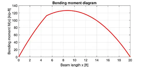
After simplifying the equation, we find that the maximum bending moment in the beam is 126.56 kip ft, occurring 8.75 ft from support A.
\(M(8.75) = 112.5 + 51.5625 – 37.5 = 126.56\,\text{kip} \cdot \text{ft}\)
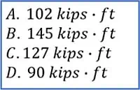
Answer selection
And there you have it! By inspecting the options given to us, we see that the correct answer is equal to C.
And that brings us to the end of this problem. We started by finding the support reactions and used them to create the shear force diagram, which helped us pinpoint where the shear equals zero—identifying the location of the maximum bending moment as 8.75 ft from support A.
Then, by integrating the shear equations, we performed a bending moment calculation and determined the maximum moment as 126.56 kip·ft.
If we were to draw the bending moment diagram, it would show a smooth curve peaking exactly at this point as shown here, confirming our result and giving us a clear picture of how the beam responds to the applied loads.
This Episode Is Brought to You By: School of PE
 School of PE has been a leading provider of exam prep courses since 2004, helping thousands of professionals achieve licensure and certification in engineering, surveying, and project management. Taught by industry experts, their courses align with the NCEES CBT format and consistently deliver pass rates above the national average. School of PE is recognized as a top-rated provider, and they are committed to student success through expert instruction and high-quality materials. Visit http://www.schoolofpe.com/ for more details and to see how they can best help you achieve your professional goals. Specialties: FE Exam Review, PE Exam Review, Surveying, and PMP.
I hope you found this week’s FE Exam article helpful. In upcoming articles, I will answer more FE Exam questions and run through more practice problems. We publish videos bi-weekly on our Pass the FE Exam YouTube Channel. Be sure to visit our page here and click the subscribe button as you’ll get expert tips and tricks – to ensure your best success – that you can’t get anywhere else. Believe me, you won’t want to miss a single video.
Lastly, I encourage you to ask questions in the comments of the videos or here on this page, and I’ll read and respond to them in future videos. So, if there’s a specific topic you want me to cover or answer, we have you covered.
I’ll see you next week… on Pass the FE Exam
Anthony Fasano, P.E., AEC PM, F. ASCE

Leave a Reply